DECODER
A decoder is a circuit that changes a code into a set of signals. It is called a decoder because it does the reverse of encoding, but we will begin our study of encoders and decoders with decoders because they are simpler to design.
A common type of decoder is the line decoder which takes an n-digit binary number and decodes it into 2n data lines. The simplest is the 1-to-2 line decoder. The truth table is:

A is the address and D is the dataline. D0 is NOT A and D1 is A. The circuit looks like:

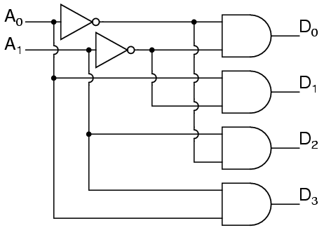
Only slightly more complex is the 2-to-4 line decoder. The truth table is:

Developed into a circuit it looks like:
Larger line decoders can be designed in a similar fashion, but just like with the binary adder there is a way to make larger decoders by combining smaller decoders. An alternate circuit for the 2-to-4 line decoder is:
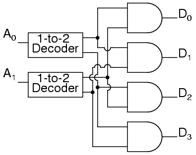
Replacing the 1-to-2 Decoders with their circuits will show that both circuits are equivalent. In a similar fashion a 3-to-8 line decoder can be made from a 1-to-2 line decoder and a 2-to-4 line decoder, and a 4-to-16 line decoder can be made from two 2-to-4 line decoders.
An encoder is a circuit that changes a set of signals into a code. Let's begin making a 2-to-1 line encoder truth table by reversing the 1-to-2 decoder truth table.

This truth table is a little short. A complete truth table would be

One question we need to answer is what to do with those other inputs? Do we ignore them? Do we have them generate an additional error output? In many circuits this problem is solved by adding sequential logic in order to know not just what input is active but also which order the inputs became active.
A more useful application of combinational encoder design is a binary to 7-segment encoder. The seven segments are given according

Our truth table is:

Deciding what to do with the remaining six entries of the truth table is easier with this circuit. This circuit should not be expected to encode an undefined combination of inputs, so we can leave them as "don't care" when we design the circuit. The boolean equations are

and the circuit is

DEMULTIPLEXERS
A demultiplexer, sometimes abbreviated dmux, is a circuit that has one input and more than one output. It is used when a circuit wishes to send a signal to one of many devices. This description sounds similar to the description given for a decoder, but a decoder is used to select among many devices while a demultiplexer is used to send a signal among many devices.
A demultiplexer is used often enough that it has its own schematic symbol

The truth table for a 1-to-2 demultiplexer is

Using our 1-to-2 decoder as part of the circuit, we can express this circuit easily

This circuit can be expanded two different ways. You can increase the number of signals that get transmitted, or you can increase the number of inputs that get passed through. To increase the number of inputs that get passed through just requires a larger line decoder. Increasing the number of signals that get transmitted is even easier.
As an example, a device that passes one set of two signals among four signals is a "two-bit 1-to-2 demultiplexer". Its circuit is

or by expressing the circuit as

shows that it could be two one-bit 1-to-2 demultiplexers without changing its expected behavior.
A 1-to-4 demultiplexer can easily be built from 1-to-2 demultiplexers as follows.

MULTIPLEXERS
A multiplexer, abbreviated mux, is a device that has multiple inputs and one output.
The schematic symbol for multiplexers is

The truth table for a 2-to-1 multiplexer is

Using a 1-to-2 decoder as part of the circuit, we can express this circuit easily.

Multiplexers can also be expanded with the same naming conventions as demultiplexers. A 4-to-1 multiplexer circuit is

That is the formal definition of a multiplexer. Informally, there is a lot of confusion. Both demultiplexers and multiplexers have similar names, abbreviations, schematic symbols and circuits, so confusion is easy. The term multiplexer, and the abbreviation mux, are often used to also mean a demultiplexer, or a multiplexer and a demultiplexer working together. So when you hear about a multiplexer, it may mean something quite different.
MAGNITUDE COMPARATOR
Three outputs are provided: “A greater than B” (OA>B), “A less than B” (OA
No comments:
Post a Comment